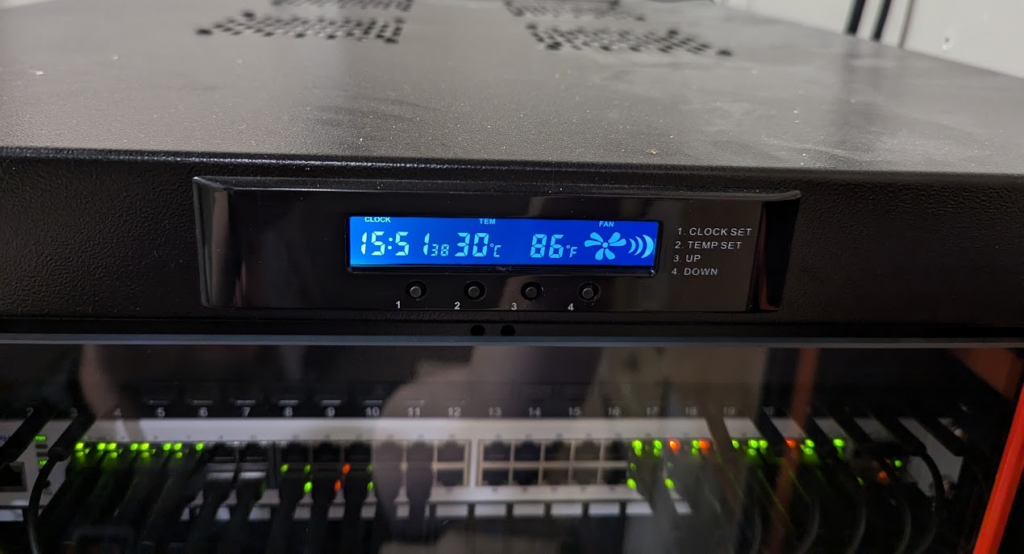
Ah, the joys of tech life – nothing beats the satisfaction of optimizing your gear to run just right. Today, I’m diving into a little project we had at our office, involving our 37U rack from Sysracks. The rack itself has been fantastic, shipped flat-packed, and built with solid instructions. It’s a four-post wonder with temperature-controlled fans and a nifty status screen to boot. However, there’s been one small hiccup: the built-in fan controller is a bit… well, let’s say, overzealous.
The Problem: A Fickle Fan
On those warm summer days in our non-environmentally controlled room, the fans kick on for about 7 seconds every minute. The reason? I don’t always like tooting our own horn (okay, maybe a little) but we have excellent cable management which allows a lot of conditioned cooler air outside the rack to move through the whole rack very quickly. The fans cool the rack just enough to drop the temperature below the fan on threshold, only to have it rise again quickly a minute later. It’s like a never-ending game of tag, and it’s driving us bonkers!
The Solution: DIY Fan Controller with an ESP8266
Rather than tearing out the entire system (I do really like the screen on the rack) or modifying any of the existing controller, I decided to integrate a custom controller with our existing setup. We’ll use an ESP8266 with a temperature sensor to create a smarter, more efficient fan controller. The idea is to set the OEM controller to an excessively low threshold (say, 20°C), ensuring it’s always providing power to the fans. We’ll then splice into that power with a relay, giving our ESP8266 the reins to manage the fans more intelligently.
What You’ll Need:
- ESP8266 Board
- DHT11 or DHT22 Module
- Relay Module
- Breadboard, Jumper Wires or Double Sided PCB Board
- Power Supply
Step-by-Step Instructions:
Installing the Arduino IDE
First, let’s install the Arduino IDE and set it up for the ESP8266.
- Download the Arduino IDE and install it.
Installing the ESP8266 Add-on in Arduino IDE
- Open the Arduino IDE, go to File > Preferences.
- Enter
http://arduino.esp8266.com/stable/package_esp8266com_index.jsoninto the “Additional Boards Manager URLs” field. Then, click the “OK” button. - *Note: if you already have the ESP32 boards URL, you can separate the URLs with a comma as follows:
https://dl.espressif.com/dl/package_esp32_index.json, http://arduino.esp8266.com/stable/package_esp8266com_index.json* - Open the Boards Manager. Go to Tools > Board > Boards Manager…
- Search for ESP8266 and press the install button for the “ESP8266 by ESP8266 Community”.
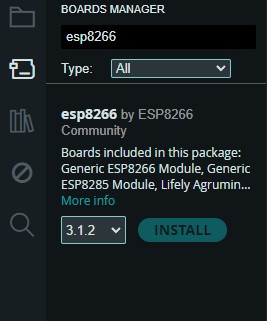
It should be installed after a few seconds.
Setting Up the ESP8266
Now, let’s get our ESP8266 up and running. You’ll need to flash it with the Arduino IDE.
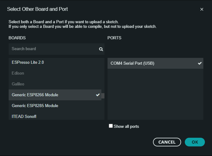
- Connect the ESP8266 to your computer via USB and select the appropriate board and port from the tools menu. If for some reason you don’t see the board/port in Arduino IDE, check Windows device manager to make sure the driver installed. In my case, I had to manually download and select the right driver for my board.
- Once connected, select the board and the correct port (COM4 in my case) and upload the basic sketch below (you may want to adjust temp trigger settings for your testing, based on your environment)
#include <ESP8266WiFi.h>
#include <DHT.h>

#define DHTPIN 2 // GPIO2 corresponds to D4 on the ESP8266
#define DHTTYPE DHT11 // Define the sensor type as DHT11
#define RELAY_PIN 5 // GPIO5 corresponds to D1 on the ESP8266

DHT dht(DHTPIN, DHTTYPE);

void setup() {
  Serial.begin(115200);
  pinMode(RELAY_PIN, OUTPUT);
  dht.begin();
}

void loop() {
  float temp = dht.readTemperature();

  if (isnan(temp)) {
    Serial.println("Failed to read from DHT sensor!");
    return;
  }

  Serial.print("Temperature: ");
  Serial.println(temp);

  if (temp > 25) {
    digitalWrite(RELAY_PIN, HIGH); // Turn on the fan
  } else {
    digitalWrite(RELAY_PIN, LOW); // Turn off the fan
  }

  delay(2000); // Wait a bit between readings
}
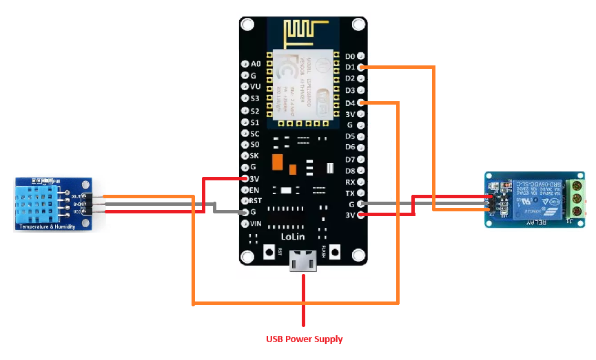
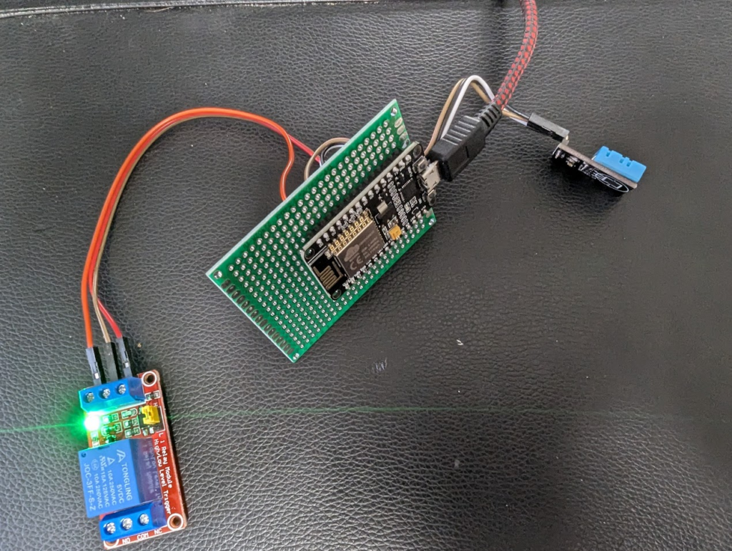
Wiring It Up
Connect your temperature sensor and relay module to the ESP8266 as follows:
- DHT11 Data to D4 (data pin), + pin to 3v on ESP8266, and – to GND on ESP8266
- Relay module trigger to D1, + pin to VIN (voltage In which in the case of using a USB power supply will be 5v), and – to GND
- Power supply connections: ensure the relay and ESP8266 are properly powered. I’m using an external USB power supply and powering directly to the USB port
Here is how mine looked in its early test stage, holding the DHT11 tightly in my hands was enough to increase the temp to triggered the relay to flip. Blowing ever so gently on it set the pin back to low and the relay opened back up!
Testing and Calibration
With everything hooked up, power on your ESP8266 and monitor the serial output. Adjust the temperature thresholds in the code as necessary to ensure the fan will kick in at the right time.
Making it Better: Adding an Off Threshold
Now that we’ve got our basic setup working, it’s time to build a better fan controller. To make our system more efficient and prevent frequent cycling, we need to add an off threshold. This way, once the fans turn on by exceeding the on threshold, they’ll stay on until the temperature drops below a set level.
Updated Code with On and Off Thresholds
#include <ESP8266WiFi.h>
#include <DHT.h>

#define DHTPIN 2 // GPIO2 corresponds to D4 on the ESP8266
#define DHTTYPE DHT11 // Define the sensor type as DHT11
#define RELAY_PIN 5 // GPIO5 corresponds to D1 on the ESP8266

DHT dht(DHTPIN, DHTTYPE);

bool fanOn = false;
const float ON_THRESHOLD = 30.0; // Temperature to turn the fan on
const float OFF_THRESHOLD = 25.0; // Temperature to turn the fan off

void setup() {
  Serial.begin(115200);
  pinMode(RELAY_PIN, OUTPUT);
  digitalWrite(RELAY_PIN, LOW); // Ensure the fan is initially off
  dht.begin();
}

void loop() {
  float temp = dht.readTemperature();

  if (isnan(temp)) {
    Serial.println("Failed to read from DHT sensor!");
    return;
  }

  Serial.print("Temperature: ");
  Serial.println(temp);

  if (!fanOn && temp > ON_THRESHOLD) {
    digitalWrite(RELAY_PIN, HIGH); // Turn on the fan
    fanOn = true;
    Serial.println("Fan turned ON");
  } else if (fanOn && temp < OFF_THRESHOLD) {
    digitalWrite(RELAY_PIN, LOW); // Turn off the fan
    fanOn = false;
    Serial.println("Fan turned OFF");
  }

  delay(2000); // Wait a bit between readings
}
Testing the Updated Setup
With the updated code, power on your ESP8266 and monitor the serial output to ensure the relay operates as expected with the new on and off thresholds.
Finalizing the Design
Now that we know everything is functioning as expected, it’s time to finalize the design a little. I used some headers on my PCB which allows me to remove the ESP8266 easily in the future for updates or software changes. Soldering all the wire connections together ensured a secure and reliable setup. With these final touches, we now have a (somewhat) more polished design that’s ready for use.
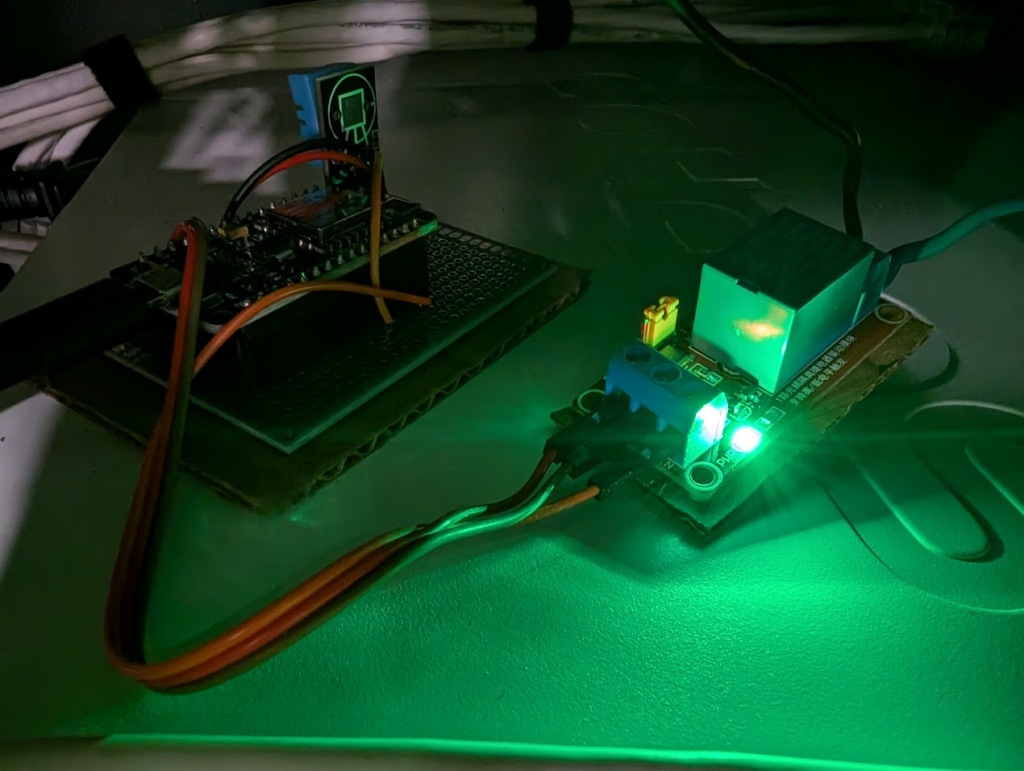
We used some wires to attach to the relay module so that it could be located closer to the fans, and also isolate our high voltage fans from our low voltage board. This not only makes the build a little safer and more durable but also simplifies any future maintenance.
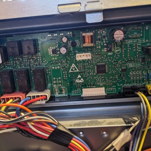
Splicing Into the Fan Power
Carefully splice into the fan power supply and connect it to the relay module. The fans in our rack use 120v, so its important to ensure you maintain safety standards – no one likes getting zapped!
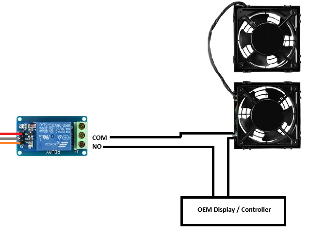
Disclaimer: Working with high voltage can be dangerous. Ensure you take all necessary precautions, and if you’re not comfortable with it, consult a professional.
Future Enhancements
The beauty of the ESP8266 (besides its cost and versatility) is its built-in WiFi. Down the line, you could expand this project to include remote monitoring or even control via a web interface.
Imagine the Possibilities
With this project in mind, the sky’s really the limit for any sort of environmental control. Consider the following applications:
- Bathroom Fan Controller: Automatically turn on the fan when humidity levels rise.
- HVAC Smart System: Control your home heating and cooling more efficiently with custom thresholds.
- Greenhouse Monitoring: Maintain optimal temperature and humidity for your plants.
By combining the existing hardware of our Sysracks controller with the flexibility of the ESP8266, we’ve created a custom solution that keeps our rack cool without the constant on-off annoyance. Plus, it was a fun project that didn’t break the bank.

3 comments on “Building a Smarter Fan Controller for Your Rack”