I pulled two DJI Spark batteries out of a drawer after months (ahem…years) of storage, plugged one into the drone, and got the same useless answer both times: LEDs 1 and 2 flashing in sequence, then dark. No charge. No life. From what I could find, DJI’s official fix is a $60-70 replacement they barely sell anymore.
So I fixed both myself instead. A bricked DJI Spark battery is almost always recoverable, because nothing is physically broken… a single Permanent Failure bit is stuck in the chip’s flash, telling it to refuse charging forever. The usual repair needs a $20 CP2112 adapter and closed-source Windows software. I didn’t have that adapter and being impatient and wanting to fly the Spark on the weekend ordering one just wasn’t on my priority list. What I did have was a pile of ESP boards.
Turns out that’s all you need. Here’s the full process, including the four hours I wasted on a wrong assumption so you don’t have to.
The Problem: Why Your Bricked DJI Spark Battery Won’t Charge
The symptom is always the same. The pack sits unused for a few months. You go to fly, the battery flashes an error pattern, and it won’t take a charge from the drone or the hub. A DJI charger left on mine for 36 hours did nothing.
This isn’t a charger problem and it isn’t (usually) a worn-out cell problem. It’s a firmware lockout. The chemistry inside is often perfectly healthy. The battery just believes it has failed.
What’s Actually Happening Inside a Bricked DJI Spark Battery
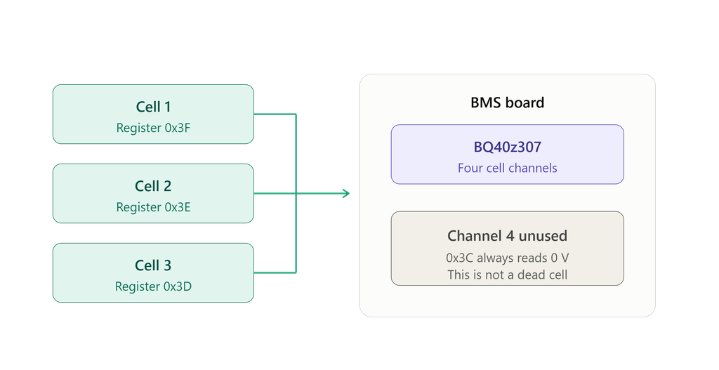
Spark packs (model MB1) are 3-cell lithium polymer batteries with a Texas Instruments BQ40z307 chip running DJI’s customized firmware, sometimes labeled BQ9003. That chip is the brain. It tracks cell voltage, temperature, and charge cycles, and it decides whether to enable the charge FET.
During long storage the chip slowly self-discharges the cells to keep them from puffing at full charge. Smart in theory. But if a cell dips under a safety threshold (around 2.5V), the chip sets a Permanent Failure (PF) flag in its data flash and stops trusting the pack. From that point on, it refuses to charge. Forever, as far as it’s concerned.
The fix is to clear that one flag. That’s the whole job. The hard part is getting the chip to actually let you.
Skip the CP2112: Revive a Bricked DJI Spark Battery With an ESP8266
Most guides send you to one of two tools. DJI Battery Killer is closed-source Windows software that talks to a $20 CP2112 USB-to-SMBus adapter through a click-based GUI. dji-firmware-tools is the open-source Python equivalent from o-gs on GitHub, built for the command line and a Raspberry Pi.
Both work. Both assume you own specific hardware. But here’s the thing: SMBus is just I2C with stricter timing, and every ESP board speaks I2C natively. If you’ve got a NodeMCU, a D1 Mini, or anything similar in a drawer, you already have the hardware side covered.
The architecture comes from GitHub user Cleric-K, who published a gist in 2025. The ESP runs a generic USB-to-I2C bridge sketch, about 100 lines, that knows nothing about batteries. It just forwards I2C traffic between USB serial and the bus. All the battery-specific brains stay in Python on your computer, running the proven dji-firmware-tools code.
I love this split. The ESP firmware is so generic you can test it against any I2C device before going anywhere near a battery. I’d already been flashing ESP chips for projects like my Sonoff S31 ESPHome conversion, so the toolchain felt familiar. Writing custom battery firmware from scratch, by contrast, would’ve been months of debugging. No thanks.
Safety First (This Part Isn’t Optional)
You’re handling lithium polymer cells that already failed a safety check. That energy sits in a thin-walled pouch, and an internal short can mean thermal runaway: flames, toxic gas, and temperatures past 500°C. I’m not trying to scare you off. I’m trying to keep you honest about the risk.
Before you connect anything, get this gear together:
- A LiPo safety bag (about $10)
- A fire-resistant surface: concrete, ceramic tile, or a metal baking sheet
- A metal container with a lid or a bucket of sand within arm’s reach
- An ABC fire extinguisher nearby
- Safety glasses and decent ventilation
- Someone in the house who knows what you’re doing
And the hard rules I genuinely won’t break:
- Pack is visibly swollen? Stop. Recycle it safely.
- Pack smells like chemicals? Stop. It’s already venting.
- Pack gets warm at any point? Disconnect and drop it in your containment vessel.
- Never leave a connected pack unattended.
If you can’t set up that infrastructure, please don’t attempt this. Pay for new batteries or hand it to someone qualified. The technical part is doable for any competent hobbyist. The safety discipline is the harder skill, honestly.
What You’ll Need
Hardware:
- An ESP8266 board (NodeMCU, D1 Mini, whatever you have)
- A USB cable for it
- 3 jumper wires
- A bench power supply with current limiting (a TP4056 module works in a pinch)
- A multimeter
Software:
- Arduino IDE with the ESP8266 board package
- Python 3.x with
pyserial - The dji-firmware-tools repo (this is the toolkit that does the real work)
- Three small scripts I’m pasting in full below: the ESP bridge sketch, the Python bridge shim, and a read-only test script
I’m not hiding any of this behind a GitHub link. Everything you need is in the code section near the bottom of this post. Copy it, read it, build it yourself.
Step 1: Wire Up the Bridge
The Spark battery’s main connector has six metal pads. Looking at the contacts, left to right:
| Pin | Signal |
|---|---|
| 1 | SCL |
| 2 | GND |
| 3 | + (Pack+) |
| 4 | + (Pack+) |
| 5 | GND |
| 6 | SDA |
You only need three of them for data. On a NodeMCU:
| Battery pin | NodeMCU pin |
|---|---|
| 1 (SCL) | D1 (GPIO5) |
| 2 (GND) | G (any ground) |
| 6 (SDA) | D2 (GPIO4) |
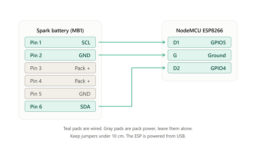
Do not connect pins 3 or 4. Those are pack power, not data. The ESP draws power from USB and the battery’s BMS runs off its own cells. Keep your wires short too, under 10cm if you can. SMBus hates long runs and you’ll chase phantom errors otherwise.
Step 2: Flash the Bridge and Test It First
Flash the bridge sketch from the Arduino IDE, plug the ESP into your PC, then check Device Manager under Ports for the COM number. On my first upload I got “ambiguous overload” warnings on requestFrom(). Those are harmless, fixed with a one-line cast, and the flash succeeds anyway. Warnings aren’t errors.
Now the step I refuse to skip: test the bridge with a known-good I2C device before any battery touches it. An LCD, an OLED, a temperature sensor, anything. Run a Python scan of the I2C bus and read from it.
If it finds your device and reads it cleanly, the bridge works. If it doesn’t, you troubleshoot here, with safe hardware, instead of later while staring at a battery and guessing. The number of “the battery is acting weird” problems that turn out to be a loose jumper is high. This is the same instinct that saved me when I built my ESPHome smart plug modem watchdog: prove the easy thing works before blaming the hard thing.
Step 3: Wake the BMS
If the pack’s been dead a while, the chip itself may be too discharged to answer. Wire up a battery, run the I2C scan, and look for device 0x0B.
Found it? The BMS is awake. Skip ahead. Nothing there? The cells are below the wake threshold and you’ve got two options.
Option A, through the connector: a current-limited bench supply at 9V and 0.3A max across pins 3 (+) and 5 (-). That trickles just enough in to wake the chip. Plenty of YouTube videos use a fresh 9V battery for this. Works, but a bench supply is safer.
Option B, cell-direct: open the case (Spark cases clip together… a guitar pick around the seam pops one open in about ten minutes with some curse words) and charge each cell with a TP4056 or bench supply at 0.2-0.5A until each hits at least 3.0V.
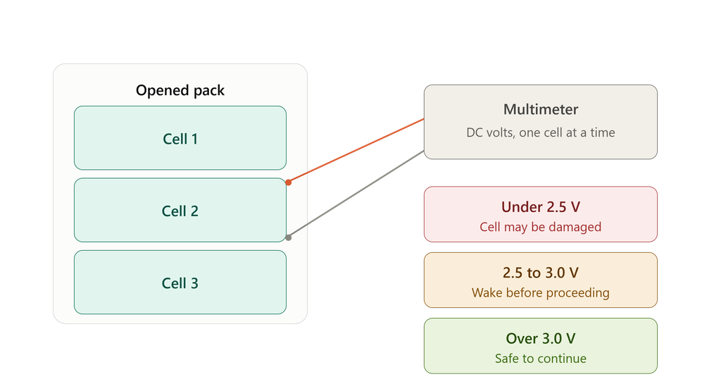
I ended up using Option B on one pack because the connector method “wasn’t working.” I later figured out that was a software bug, not a hardware failure. The cells had been charging fine the whole time. More on that mistake below.
Step 4: Reading a Bricked DJI Spark Battery (Read-Only and Safe)
This is where you confirm everything before writing anything. With the battery wired and the BMS awake:
python comm_sbs_bqctrl.py -vvv -b i2c:1 -c BQ40z307 -a 0x0b read PFStatusYou’ll see a “PEC checksum” error in the output. That’s a Python validation quirk, not a real fault. The raw bytes right above it are what count. Look for 04 01 00 00 00 d8. That 01 means the PF flag is set.
Read each cell next:
python comm_sbs_bqctrl.py -vvv -b i2c:1 -c BQ40z307 -a 0x0b read Cell0Voltage
python comm_sbs_bqctrl.py -vvv -b i2c:1 -c BQ40z307 -a 0x0b read Cell1Voltage
python comm_sbs_bqctrl.py -vvv -b i2c:1 -c BQ40z307 -a 0x0b read Cell2Voltage
python comm_sbs_bqctrl.py -vvv -b i2c:1 -c BQ40z307 -a 0x0b read Cell3Voltage
Decode the raw response as little-endian millivolts. So 1e 0b reads as 0x0b1e, which is 3038 mV.
Read this part twice. The BQ40z307 has four cell registers, but the Spark only uses three. Register 0x3C (Cell3Voltage) is the unused fourth channel and always reads 0V. Your real cells live at 0x3F, 0x3E, and 0x3D, labeled Cell0 through Cell2. If you don’t know that, you’ll swear you have a dead cell when you absolutely do not.
Step 5: The Unseal Key That Standard Guides Get Wrong
Here’s the part almost every tutorial fumbles.
The standard unseal for TI BQ40-family chips uses a 32-bit key sent as two 16-bit halves, 0x0414 and 0x3672, and dji-firmware-tools uses that default. Most guides tell you to run sealing Unseal and call it done.
On the Spark, that doesn’t work. The chip accepts the bytes and prints “Trigger SUCCESS,” but it never enters the security state you need. So your PF clear runs, reports success, and PFStatus stays stuck at 0x01 no matter how many times you try. I hit that wall for hours.
The Spark uses a custom 32-bit unseal key: 0xCCDF7EE0. It’s confirmed in dji-firmware-tools issues #232, #258, and #318 by multiple users, and it’s nowhere in the main README. The correct command:
python comm_sbs_bqctrl.py -vvv -b i2c:1 -c BQ40z307 -a 0x0b sealing --i32key 0xCCDF7EE0 UnsealWatch the OperationStatus value in the output. With the wrong key it lands somewhere like 0x00007780. With the right one you’ll see a clearly different state. Mine jumped to 0x00007280. That change is your proof the chip actually unsealed.
Why the Standard Unseal Key Doesn’t Work on the DJI Spark
Short version: DJI shipped OEM-customized firmware, and OEM firmware often ships OEM keys. The default TI keys reach a lower security level than PF reset needs. The chip happily acknowledges them, which is exactly why this is so easy to miss. “Command accepted” is not the same as “command did something.” Burn that into your brain before you write anything to a battery.
Step 6: Clear the PF Flag, Reset, and Seal
With a real unseal in place, the clear finally takes:
python comm_sbs_bqctrl.py -vvv -b i2c:1 -c BQ40z307 -a 0x0b trigger ManufacturerAccess.PermanentFailDataResetVerify it:
python comm_sbs_bqctrl.py -vvv -b i2c:1 -c BQ40z307 -a 0x0b read PFStatusYou want 04 00 00 00 00 ce. That’s PFStatus 0x00. Flag cleared. If you still see 0x01, your unseal didn’t land. Double-check you passed --i32key 0xCCDF7EE0 and run the unseal-then-clear sequence again.
Then commit with a device reset, wait about 5 seconds for the reboot, confirm PFStatus is still 0x00, and re-seal:
python comm_sbs_bqctrl.py -vvv -b i2c:1 -c BQ40z307 -a 0x0b trigger ManufacturerAccess.DeviceReset
python comm_sbs_bqctrl.py -vvv -b i2c:1 -c BQ40z307 -a 0x0b sealing Seal
Reviving the Bricked DJI Spark Battery: The Moment of Truth
Disconnect everything from the battery. Press its power button. Instead of the flash-and-die error pattern, you should get a real charge-level reading: one or two LEDs holding steady for a few seconds.
Plug it into the drone or the charging hub and add USB power. Then stay with it. Hand-check the pack every couple of minutes. If it stays cool and the drone’s charge LEDs come on normally, you’ve done it.
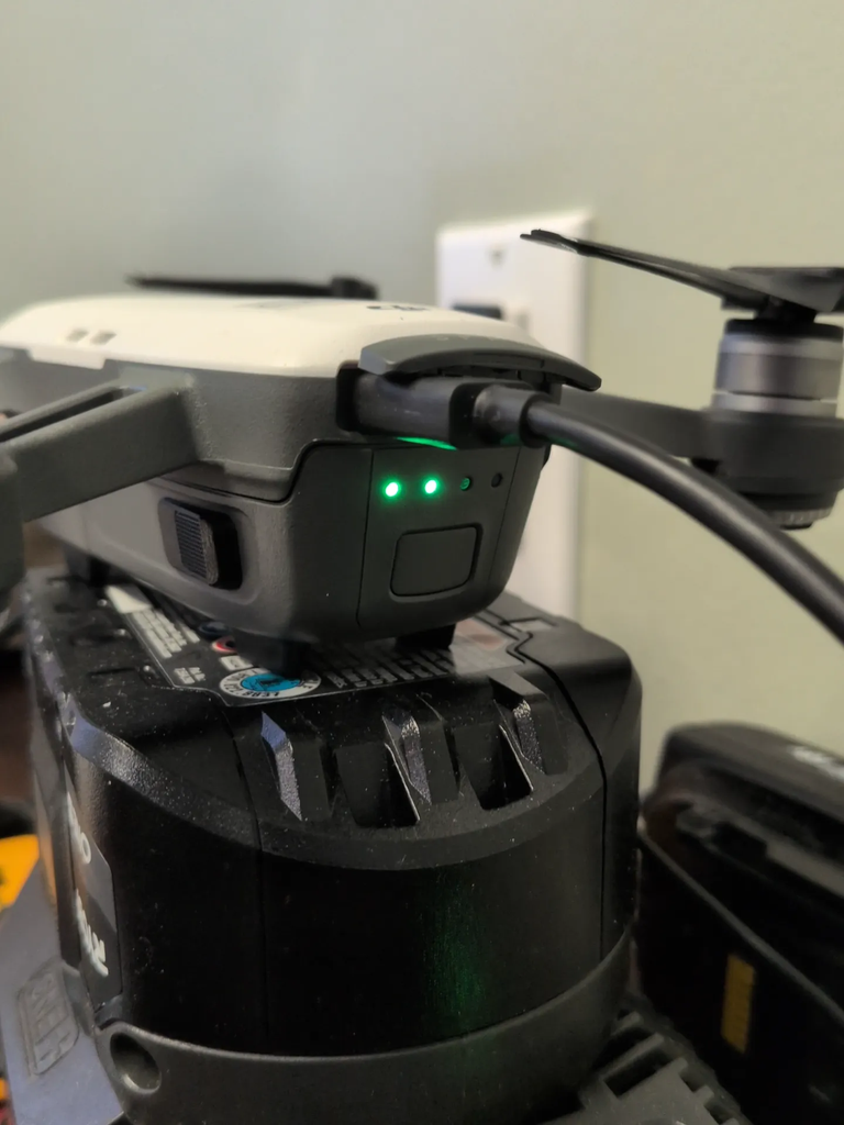
Both of mine charged within an hour of my finding the right key. The second pack started in worse shape, but it still cleared at 2.6-2.7V per cell rather than waiting for a full 3.0V. A little gamble that paid off.
What I Got Wrong (So You Don’t Have To)
This took me about four hours, not the two it should have. Honesty’s the whole point of this blog, so here are the mistakes.
I misread the chip’s cell layout for half the night. Both packs showed “cell 3 = 0V,” and I decided that meant a dead cell on each. I built hours of wrong work on that. It was the unused fourth channel the entire time. Lesson: when two independent units show the exact same failure, suspect your interpretation before the hardware.
I chased a PEC-checksum rabbit hole, writing CRC code to fix a problem that didn’t exist. Real engineering, totally unrelated to the actual issue.
And my searches never surfaced the unseal key. Three rounds of digging and 0xCCDF7EE0 stayed hidden in GitHub issues I’d technically opened but hadn’t read carefully. A second research pass found it in a few minutes. Sometimes the answer’s already in your browser tabs and you just haven’t read closely enough.
The meta-lesson? Read-only first, always. Understand what you’re looking at before you write a single byte.
The Code: Build It Yourself
No GitHub repo, no gist hunting. Here’s everything I actually used. Two pieces aren’t mine and deserve credit: the heavy lifting is done by dji-firmware-tools by o-gs (grab comm_sbs_bqctrl.py and the comm_sbs_chips/ folder from there), and the bridge concept comes from Cleric-K, who published the original ESP-as-I2C-bridge idea. The three scripts below are my own take on that approach. Read them before you run them. That’s the whole point of posting them instead of a download link.
The ESP bridge sketch
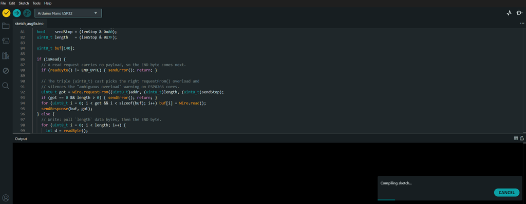
Flash this to the ESP8266 with the Arduino IDE. It’s a dumb pipe. It forwards framed I2C transactions between USB serial and the bus, and it knows nothing about batteries… which is exactly why you can test it against any I2C device first.
/*
 * esp8266_i2c_bridge.ino
 *
 * Generic USB-to-I2C (SMBus) bridge for an ESP8266 (NodeMCU / D1 Mini).
 * The ESP knows NOTHING about batteries. It just forwards framed I2C
 * transactions between the USB serial port and the I2C bus. All the
 * battery smarts live in Python on the PC (dji-firmware-tools plus the
 * smbus2.py shim).
 *
 * Wire protocol (matches smbus2.py and i2c_bridge_test.py exactly):
 *
 *   PC  -> ESP:  [0xAA][addr_rw][len_stop][data...][0x55]
 *       addr_rw  = (i2c_addr << 1) | rw       rw: 1 = read, 0 = write
 *       len_stop = length | (0x80 if a STOP should follow this transfer)
 *                  length = data bytes to write, or bytes to read (0..127)
 *       data...  = present only on a write
 *
 *   ESP -> PC:   [0xAA][resp_len][data...][0x55]   on success
 *                [0xAA][0xFF][0x55]                on I2C error (NACK/timeout)
 *       resp_len = bytes that follow (0 is a plain write ack)
 *
 * A write sent with the STOP bit clear leaves the bus in repeated-start
 * state, so the read that follows targets the register just written.
 *
 * Wiring (NodeMCU):  SDA -> D2 (GPIO4),  SCL -> D1 (GPIO5),  GND -> GND.
 * Do NOT wire battery pack power (connector pins 3/4) to the ESP.
 */

#include <Wire.h>

#define START_BYTE 0xAA
#define END_BYTE   0x55
#define ERR_BYTE   0xFF

#define SDA_PIN 4   // D2 on a NodeMCU
#define SCL_PIN 5   // D1 on a NodeMCU

static const unsigned long BYTE_TIMEOUT_MS = 50;

// Read one byte from serial with a timeout. Returns -1 if nothing arrives.
int readByte() {
  unsigned long start = millis();
  while (!Serial.available()) {
    if (millis() - start > BYTE_TIMEOUT_MS) return -1;
    yield();
  }
  return Serial.read();
}

void sendError() {
  Serial.write(START_BYTE);
  Serial.write(ERR_BYTE);
  Serial.write(END_BYTE);
}

void sendResponse(const uint8_t *data, uint8_t len) {
  Serial.write(START_BYTE);
  Serial.write(len);
  for (uint8_t i = 0; i < len; i++) Serial.write(data[i]);
  Serial.write(END_BYTE);
}

void setup() {
  Serial.begin(115200);
  Wire.begin(SDA_PIN, SCL_PIN);
  Wire.setClock(100000);            // SMBus standard 100 kHz
  Wire.setClockStretchLimit(1500);  // be patient with a sleepy BMS
}

void loop() {
  // Wait for a start byte.
  int b = readByte();
  if (b != START_BYTE) return;

  int addrRw  = readByte();
  int lenStop = readByte();
  if (addrRw < 0 || lenStop < 0) return;

  uint8_t addr     = (uint8_t)addrRw >> 1;
  bool    isRead   = (addrRw & 0x01);
  bool    sendStop = (lenStop & 0x80);
  uint8_t length   = (lenStop & 0x7F);

  uint8_t buf[140];

  if (isRead) {
    // A read request carries no payload, so the END byte comes next.
    if (readByte() != END_BYTE) { sendError(); return; }

    // The triple (uint8_t) cast picks the right requestFrom() overload and
    // silences the "ambiguous overload" warning on ESP8266 cores.
    uint8_t got = Wire.requestFrom((uint8_t)addr, (uint8_t)length, (uint8_t)sendStop);
    if (got == 0 && length > 0) { sendError(); return; }
    for (uint8_t i = 0; i < got && i < sizeof(buf); i++) buf[i] = Wire.read();
    sendResponse(buf, got);
  } else {
    // Write: pull `length` data bytes, then the END byte.
    for (uint8_t i = 0; i < length; i++) {
      int d = readByte();
      if (d < 0) { sendError(); return; }
      buf[i] = (uint8_t)d;
    }
    if (readByte() != END_BYTE) { sendError(); return; }

    Wire.beginTransmission(addr);
    for (uint8_t i = 0; i < length; i++) Wire.write(buf[i]);
    uint8_t res = Wire.endTransmission(sendStop);  // 0 = device ACKed
    if (res != 0) { sendError(); return; }

    sendResponse(nullptr, 0);  // empty ack
  }
}
The read-only test script
Run this first, against a known-good I2C device and then against a battery. It scans the bus, finds the smart battery at 0x0B, and reads pack voltage and the three real cells. Pure read-only, no writes. If this works, your bridge works. Set SERIAL_PORT to match your ESP’s COM port.
#!/usr/bin/env python3
"""
i2c_bridge_test.py

Test script for the ESP I2C bridge. Reads cell voltages from a DJI Spark
(or similar BQ40z307-based) battery.

CELL MAPPING (corrected):
  The BQ40z307 chip is 4-cell-capable but the Spark uses only 3 cells.
  The unused channel (register 0x3C) always reads 0V.

  Register 0x3F = Cell 1 (real)
  Register 0x3E = Cell 2 (real)
  Register 0x3D = Cell 3 (real)
  Register 0x3C = unused (always 0V, hidden)
"""

import serial
import time
import sys

SERIAL_PORT = 'COM7'   # change to match your CH340 COM port
BAUD = 115200
START_BYTE = 0xAA
END_BYTE = 0x55


class BridgeError(Exception):
    pass


class I2CBridge:
    def __init__(self, port, baud=BAUD):
        print(f"Opening serial port {port} at {baud} baud...")
        self.ser = serial.Serial(port, baud, timeout=0.5)
        print("Waiting for ESP to boot...")
        time.sleep(2.5)
        self.ser.reset_input_buffer()
        print("Bridge ready.\n")

    def close(self):
        if self.ser:
            self.ser.close()
            self.ser = None

    def _send_packet(self, addr, is_read, data_or_len, is_stop=True):
        packet = bytearray([START_BYTE])
        addr_byte = (addr << 1) | (1 if is_read else 0)
        packet.append(addr_byte)
        length = data_or_len if is_read else len(data_or_len)
        if length > 0x7F:
            raise BridgeError(f"Length {length} exceeds 127")
        len_byte = length | (0x80 if is_stop else 0)
        packet.append(len_byte)
        if not is_read:
            packet.extend(data_or_len)
        packet.append(END_BYTE)
        self.ser.reset_input_buffer()
        self.ser.write(bytes(packet))
        start = self.ser.read(1)
        if len(start) == 0 or start[0] != START_BYTE:
            raise BridgeError(f"No response or bad start byte: {start!r}")
        length_byte = self.ser.read(1)
        if len(length_byte) == 0:
            raise BridgeError("Response truncated (no length byte)")
        if length_byte[0] == 0xFF:
            end = self.ser.read(1)
            if len(end) and end[0] == END_BYTE:
                raise BridgeError("I2C error (NACK or timeout from device)")
            raise BridgeError("I2C error and malformed response")
        resp_len = length_byte[0]
        data = self.ser.read(resp_len) if resp_len > 0 else b''
        end = self.ser.read(1)
        if len(end) == 0 or end[0] != END_BYTE:
            raise BridgeError(f"Bad end byte: {end!r}")
        return data

    def probe(self, addr):
        try:
            self._send_packet(addr, is_read=False, data_or_len=[], is_stop=True)
            return True
        except BridgeError:
            return False

    def read_register(self, addr, reg, count=2):
        self._send_packet(addr, is_read=False, data_or_len=[reg], is_stop=False)
        return self._send_packet(addr, is_read=True, data_or_len=count, is_stop=True)


def scan_bus(bridge):
    print("Scanning I2C bus...")
    print("    0  1  2  3  4  5  6  7  8  9  A  B  C  D  E  F")
    found = []
    for row in range(0, 0x80, 0x10):
        line = f"{row:02X}: "
        for col in range(16):
            addr = row + col
            if addr < 0x03 or addr > 0x77:
                line += "   "
                continue
            if bridge.probe(addr):
                line += f"{addr:02X} "
                found.append(addr)
            else:
                line += "-- "
        print(line)
    print()
    if found:
        print(f"Found {len(found)} device(s):")
        for addr in found:
            label = ""
            if addr == 0x0B:
                label = "  <-- Smart Battery"
            print(f"  0x{addr:02X}{label}")
    else:
        print("No I2C devices found.")
    print()
    return found


def main():
    try:
        bridge = I2CBridge(SERIAL_PORT)
    except serial.SerialException as e:
        print(f"\nCould not open serial port: {e}")
        sys.exit(1)

    try:
        devices = scan_bus(bridge)
        if 0x0B not in devices:
            print("No battery detected on the bus.")
            return

        print("=" * 60)
        print("SMART BATTERY DETECTED at 0x0B")
        print("=" * 60)
        print("Reading basic info (READ-ONLY, no writes):\n")

        try:
            # Pack voltage (SBS standard register 0x09)
            v = bridge.read_register(0x0B, 0x09, 2)
            if len(v) == 2:
                mv = v[0] | (v[1] << 8)
                print(f"  Pack voltage:    {mv} mV ({mv/1000.0:.2f} V)")

            # Temperature (0.1 K)
            t = bridge.read_register(0x0B, 0x08, 2)
            if len(t) == 2:
                tk = t[0] | (t[1] << 8)
                print(f"  Temperature:     {tk/10.0 - 273.15:.1f} C")

            # Cycle count
            c = bridge.read_register(0x0B, 0x17, 2)
            if len(c) == 2:
                cycles = c[0] | (c[1] << 8)
                print(f"  Cycle count:     {cycles}")

            # === CORRECTED CELL MAPPING ===
            # The BQ40z307 is 4-cell-capable. On a 3-cell Spark pack:
            #   Register 0x3F = Cell 1 (real)
            #   Register 0x3E = Cell 2 (real)
            #   Register 0x3D = Cell 3 (real)
            #   Register 0x3C = unused empty channel (always 0V) -- skip
            print()
            cell_regs = [(0x3F, "Cell 1"), (0x3E, "Cell 2"), (0x3D, "Cell 3")]
            cell_voltages = []
            for reg, name in cell_regs:
                cv = bridge.read_register(0x0B, reg, 2)
                if len(cv) == 2:
                    cmv = cv[0] | (cv[1] << 8)
                    cell_voltages.append(cmv)
                    print(f"  {name} voltage:  {cmv} mV")

            # Imbalance check
            if len(cell_voltages) == 3:
                spread = max(cell_voltages) - min(cell_voltages)
                print(f"  Imbalance:       {spread} mV")
                if spread > 100:
                    print(f"  WARNING: cell imbalance over 100 mV")

        except BridgeError as e:
            print(f"  Read failed: {e}")

    finally:
        bridge.close()


if __name__ == '__main__':
    main()
The Python bridge shim (smbus2.py)
This is what lets dji-firmware-tools talk to the ESP instead of a real SMBus adapter. Drop it in the same folder as comm_sbs_bqctrl.py so it gets imported in place of the real smbus2. Set SERIAL_PORT to your COM port.
One honest note: the PEC (checksum) handling in here was me chasing a theory that turned out to be a dead end. It doesn’t hurt anything and the reads/writes still work with it on, so I’ve left it as-is rather than pretend I wrote it clean the first time. If you want the bare-bones version, flip APPEND_WRITE_PEC and VALIDATE_READ_PEC to False.
"""
smbus2.py - PEC-aware shim that lets dji-firmware-tools talk to our ESP bridge.

WHAT THIS DOES vs. the original Cleric-K shim:
  - Computes SMBus PEC (Packet Error Code, CRC-8 poly 0x07) on every WRITE
    and appends it to the byte stream. This is what real SMBus masters do.
  - Validates PEC on every READ. If our PEC matches the chip's PEC byte,
    we know our CRC math is correct.

CONFIG: edit SERIAL_PORT below.
"""

import serial
import time

# === EDIT THIS ===
SERIAL_PORT = 'COM7'
# =================

BAUD = 115200
START_BYTE = 0xAA
END_BYTE = 0x55

VALIDATE_READ_PEC = True
APPEND_WRITE_PEC = True


def crc8_smbus(data_bytes):
    """SMBus PEC: CRC-8 with polynomial 0x07, init 0x00."""
    crc = 0x00
    for byte in data_bytes:
        crc ^= byte
        for _ in range(8):
            if crc & 0x80:
                crc = ((crc << 1) ^ 0x07) & 0xFF
            else:
                crc = (crc << 1) & 0xFF
    return crc


class SMBusError(Exception):
    pass


class SMBus:
    """Drop-in replacement for python-smbus / smbus2 that talks to our ESP
    bridge over USB serial."""

    def __init__(self, bus=1):
        self.ser = None
        self._connect()
        self.pec_checks = 0
        self.pec_failures = 0

    def _connect(self):
        if self.ser is None or not self.ser.is_open:
            self.ser = serial.Serial(SERIAL_PORT, BAUD, timeout=0.5)
            time.sleep(2.5)
            self.ser.reset_input_buffer()

    def close(self):
        if self.ser:
            self.ser.close()
            self.ser = None

    def _bridge_transact(self, addr, is_read, data_or_len, is_stop=True):
        packet = bytearray([START_BYTE])
        addr_byte = (addr << 1) | (1 if is_read else 0)
        packet.append(addr_byte)
        length = data_or_len if is_read else len(data_or_len)
        len_byte = length | (0x80 if is_stop else 0)
        packet.append(len_byte)
        if not is_read:
            packet.extend(data_or_len)
        packet.append(END_BYTE)

        self.ser.reset_input_buffer()
        self.ser.write(bytes(packet))

        start = self.ser.read(1)
        if len(start) == 0 or start[0] != START_BYTE:
            raise SMBusError(f"No response or bad start byte: {start!r}")

        length_byte = self.ser.read(1)
        if len(length_byte) == 0:
            raise SMBusError("Response truncated (no length byte)")

        if length_byte[0] == 0xFF:
            end = self.ser.read(1)
            raise SMBusError("I2C error (NACK or timeout from device)")

        resp_len = length_byte[0]
        data = self.ser.read(resp_len) if resp_len > 0 else b''
        end = self.ser.read(1)
        if len(end) == 0 or end[0] != END_BYTE:
            raise SMBusError(f"Bad end byte: {end!r}")
        return data

    def write_byte(self, addr, value):
        addr_w = (addr << 1) | 0
        if APPEND_WRITE_PEC:
            pec = crc8_smbus([addr_w, value])
            data = [value, pec]
        else:
            data = [value]
        self._bridge_transact(addr, is_read=False, data_or_len=data, is_stop=True)

    def write_byte_data(self, addr, cmd, value):
        addr_w = (addr << 1) | 0
        if APPEND_WRITE_PEC:
            pec = crc8_smbus([addr_w, cmd, value])
            data = [cmd, value, pec]
        else:
            data = [cmd, value]
        self._bridge_transact(addr, is_read=False, data_or_len=data, is_stop=True)

    def write_word_data(self, addr, cmd, value):
        lo = value & 0xFF
        hi = (value >> 8) & 0xFF
        addr_w = (addr << 1) | 0
        if APPEND_WRITE_PEC:
            pec = crc8_smbus([addr_w, cmd, lo, hi])
            data = [cmd, lo, hi, pec]
        else:
            data = [cmd, lo, hi]
        self._bridge_transact(addr, is_read=False, data_or_len=data, is_stop=True)

    def write_block_data(self, addr, cmd, values):
        block_len = len(values)
        payload = [cmd, block_len] + list(values)
        addr_w = (addr << 1) | 0
        if APPEND_WRITE_PEC:
            pec = crc8_smbus([addr_w] + payload)
            payload.append(pec)
        self._bridge_transact(addr, is_read=False, data_or_len=payload, is_stop=True)

    def write_i2c_block_data(self, addr, cmd, values):
        self.write_block_data(addr, cmd, values)

    def read_byte_data(self, addr, cmd):
        self._bridge_transact(addr, is_read=False, data_or_len=[cmd], is_stop=False)
        resp = self._bridge_transact(addr, is_read=True, data_or_len=2, is_stop=True)
        if len(resp) < 1:
            raise SMBusError("Short response on read_byte_data")
        value = resp[0]
        if VALIDATE_READ_PEC and len(resp) >= 2:
            addr_w = (addr << 1) | 0
            addr_r = (addr << 1) | 1
            expected_pec = crc8_smbus([addr_w, cmd, addr_r, value])
            self._check_pec("read_byte_data", expected_pec, resp[1])
        return value

    def read_word_data(self, addr, cmd):
        self._bridge_transact(addr, is_read=False, data_or_len=[cmd], is_stop=False)
        resp = self._bridge_transact(addr, is_read=True, data_or_len=3, is_stop=True)
        if len(resp) < 2:
            raise SMBusError(f"Short response on read_word_data: {resp.hex()}")
        lo, hi = resp[0], resp[1]
        value = lo | (hi << 8)
        if VALIDATE_READ_PEC and len(resp) >= 3:
            addr_w = (addr << 1) | 0
            addr_r = (addr << 1) | 1
            expected_pec = crc8_smbus([addr_w, cmd, addr_r, lo, hi])
            self._check_pec("read_word_data", expected_pec, resp[2])
        return value

    def read_block_data(self, addr, cmd):
        self._bridge_transact(addr, is_read=False, data_or_len=[cmd], is_stop=False)
        resp = self._bridge_transact(addr, is_read=True, data_or_len=34, is_stop=True)
        if len(resp) < 1:
            raise SMBusError("Short response on read_block_data")
        block_len = resp[0]
        if block_len > 32:
            raise SMBusError(f"Invalid block length: {block_len}")
        data = list(resp[1:1 + block_len])
        if VALIDATE_READ_PEC and len(resp) >= 1 + block_len + 1:
            addr_w = (addr << 1) | 0
            addr_r = (addr << 1) | 1
            pec_bytes = [addr_w, cmd, addr_r, block_len] + data
            expected_pec = crc8_smbus(pec_bytes)
            actual_pec = resp[1 + block_len]
            self._check_pec("read_block_data", expected_pec, actual_pec)
        return data

    def read_i2c_block_data(self, addr, cmd, length):
        self._bridge_transact(addr, is_read=False, data_or_len=[cmd], is_stop=False)
        resp = self._bridge_transact(addr, is_read=True, data_or_len=length + 1, is_stop=True)
        if len(resp) < length:
            raise SMBusError(f"Short response: got {len(resp)}, expected {length+1}")
        data = list(resp[:length])
        if VALIDATE_READ_PEC and len(resp) >= length + 1:
            addr_w = (addr << 1) | 0
            addr_r = (addr << 1) | 1
            pec_bytes = [addr_w, cmd, addr_r] + data
            expected_pec = crc8_smbus(pec_bytes)
            actual_pec = resp[length]
            self._check_pec("read_i2c_block_data", expected_pec, actual_pec)
        return data

    def _check_pec(self, op_name, expected, actual):
        self.pec_checks += 1
        if expected != actual:
            self.pec_failures += 1
            print(f"  [PEC WARN] {op_name}: expected 0x{expected:02x}, got 0x{actual:02x}")


# Compatibility alias
SMBusWrapper = SMBus
That’s the full toolkit. The bridge sketch is generic enough to reuse for any I2C poking you want to do later, which is honestly half the reason I like this approach.
Don’t Fly It Right Away
A revived battery isn’t a new one. The cells got stressed, the BMS went through a forced reset, and you don’t yet know if the pack holds capacity under real load. So ease into it.
- Let it sit at full charge for 30 minutes. Check for warmth, swelling, or voltage sag. A pack that fails the rest test isn’t ready.
- First flight stays low, over grass, with your eyes on the battery percentage.
- Land at 30%, not your usual 15-20%.
- Sudden voltage drop on the display? Land now.
Don’t trust a revived pack with important footage or flights over people until it’s logged several uneventful cycles.
One more thing worth saying plainly: this 0xCCDF7EE0 key is Spark-specific. Mavic and Phantom packs reportedly use different custom keys, also undocumented in the main README, so don’t expect this exact value to work on those. Check the dji-firmware-tools issues for your model.
The Spark’s an old drone now, and a lot of owners have a perfectly good battery sitting dead in a drawer because the only “fix” DJI offers is a part they don’t even stock. If you’ve got basic electronics chops, you can bring it back for about $5 of hardware you probably already own. Not every pack survives… cells held too low for too long can develop real damage no software touches, maybe 30-40% of long-storage bricks. The rest deserve a respectful trip to recycling. Thankfully, both of mine made it.